Beethoven Hardware Stack
A design of an accelerator is broken down into two parts. First, there is the functional unit implementation, the core. You would typically implement this in your HDL of choice. We are huge fans of Chisel HDL, but we do understand the necessity of [System]Verilog, so we have added various utilities to make it easier to integrate external Verilog modules into your design.
Second, there is the accelerator configuration. The configuration informs Beethoven how to build your accelerator:
- What cores do you want in your design?
- How many of each?
- How are they connected to memory?
Before we dive into the configuration, let's look at a simple accelerator core implementation.
A Basic Example
As an example, let's look at how we might implement a vector addition kernel in Beethoven.
// C++ implementation for Vector addition
void vector_add(int *a, int *b, int *out, int len) {
    for (int i = 0; i < len; ++i)
        out[i] = a[i] + b[i];
}

int main() {
    int array_len = 1024;
    int *a   = (int*)malloc(sizeof(int) * array_len);
    int *b   = (int*)malloc(sizeof(int) * array_len);
    int *out = (int*)malloc(sizeof(int) * array_len);
    // initialize vectors
    vector_add(a, b, out, array_len);
    return 0;
}
We can start by implementing a module for performing the addition itself. Beethoven is designed in Chisel HDL, but if you prefer Verilog, you can integrate Verilog code into Chisel using its Blackbox abstraction.
- Chisel
- Verilog
class VectorAdd extends Module {
  val io = IO(new Bundle {
    val vec_a = Flipped(Decoupled(UInt(32.W)))
    val vec_b = Flipped(Decoupled(UInt(32.W)))
    val vec_out = Decoupled(UInt(32.W))
  })
  // only consume an element when everyone's ready to move
  val can_consume = io.vec_a.valid && io.vec_b.valid && io.vec_out.ready
  io.vec_out.valid := can_consume
  io.vec_a.ready := can_consume
  io.vec_b.ready := can_consume
  io.vec_out.bits := io.vec_a.bits + io.vec_b.bits
}
module VectorAdd (
	input clk,
	input reset,
	input [31:0]  vec_a_bits,
	input 	      vec_a_valid,
	output		  vec_a_ready,
	input [31:0]  vec_b_bits,
	input 		  vec_b_valid,
	output		  vec_b_ready,
	output [31:0] vec_out_bits,
	output 		  vec_out_valid,
	input		  vec_out_ready );
wire can_consume = vec_a_valid && vec_b_valid && vec_out_ready;

assign vec_out_bits = vec_a_bits + vec_b_bits;

assign vec_out_valid = can_consume;
assign vec_a_ready = can_consume;
assign vec_b_ready = can_consume;

endmodule
Now that we have the addition implemented, how would we go about using this on real hardware? The reality: it depends. The hardware you have is likely going to have a number of general purpose memory interfaces. You'll need to provide addresses and a variety of protocol-specific metadata to access your input vectors and write your output vector. Some examples of how one would do this using general purpose protocols can be seen here.
Using these general-purpose protocols typically distracts from your core implementation because strict compliance with the protocol and managing the physical realities of the protocol (i.e., it may have a fixed location on hardware) has little to do with your implementation. Let's take a look at how we can use Beethoven abstractions to simplify our vector addition kernel.
Boilerplate
First, let's start with the boilerplate. For each Beethoven Core, you have a hardware implementation and an associated Configuration. Click on the tabs to see how we modify the implementation and configuration at each step.
- Implementation
- Configuration
import chisel3._
import chisel3.util._
import beethoven._

class VectorAddCore()(implicit p: Parameters) extends AcceleratorCore {
	// implementation goes here
}
class VecAddConfig extends AcceleratorConfig(
	AcceleratorSystemConfig(
		nCores = 1,
		name = "myVectorAdd",
		moduleConstructor = ModuleBuilder(p => new VectorAdd()(p))
	)
)
AcceleratorCore is the top-level Beethoven abstraction for a user's design. You can modularize
your implementation in whatever fashion you'd like, but the module that you plan to expose to the
top-level memory interfaces needs to be an AcceleratorCore.
Each AcceleratorCore has an associated AcceleratorConfig that describes some high-level
details that allow you to provide some high-level build parameters for your accelerator. One that
you can see here is nCores. You can increase the number of independent cores on your accelerator
by simply increasing this parameter.
Host-Accelerator Communication
Next, we need to get the addresses for each of our vectors. The host CPU will need to send these
over to the accelerator. To expose an accelerator function to the CPU, we expose a BeethovenIO
in a similar way to IO() in Chisel.
- Implementation
- Configuration
- Generated C++
// inside the AcceleratorCore
val my_io = BeethovenIO(new AccelCommand("vector_add") {
	val vec_a_addr = Address()
	val vec_b_addr = Address()
	val vec_out_addr = Address()
	val vector_length = UInt(32.W)
}, EmptyAccelResponse())
class VecAddConfig extends AcceleratorConfig(
        AcceleratorSystemConfig(
                nCores = 1,
                name = "myVectorAdd",
                moduleConstructor = ModuleBuilder(p => new VectorAdd()(p))
        )
)
namespace myVectorAdd {
        beethoven::response_handle<bool> vector_add(
		uint16_t core_id,
		uint32_t vector_length,
		beethoven::remote_ptr vec_a_addr,
		beethoven::remote_ptr vec_b_addr,
		beethoven::remote_ptr vec_out_addr);
};
The above snippet does several things.
First, the command and response are both provided with names.
The name vector_add, allows Beethoven to generate a software interface for your code
that will be called vector_add.
This function will take in the the arguments as specified and return an acknowledgement.
Responses can also carry payload, but we exclude that functionality for simplicity in this example.
Second, you'll notice Address() is not a typical Verilog or Chisel type. We provide
it to abstract away from platform-specific address-widths and provide a uniform interface.
To read more about the full specification of BeethovenIO, click here.
Adding Memory Interfaces
Now that we have a way of obtaining the necessary function arguments from the host, we need to read
our operands from memory. We can do this by declaring a Reader. Usually you would have to read up
on the available interfaces for your platform - here, there's no need, just declare them.
- Implementation
- Configuration
// inside AcceleratorCore
val vec_a_reader = getReaderModule("vec_a")
val vec_b_reader = getReaderModule("vec_b")
val vec_out_writer = getWriterModule("vec_out")
class VecAddConfig extends AcceleratorConfig(
        AcceleratorSystemConfig(
                nCores = 1,
                name = "myVectorAdd",
                moduleConstructor = ModuleBuilder(p => new VectorAdd()(p)),
		memoryChannelConfig = List(
			ReadChannelConfig("vec_a", dataBytes = 4),
			ReadChannelConfig("vec_b", dataBytes = 4),
			WriteChannelConfig("vec_out", dataBytes = 4)
		)
        )
)
For each reader/writer, the physical data bus width is specified in the configuration. These can be made arbitrarily large or small with some restrictions. Read more here.
Full Implementation
Finally, we have all of the primitives we need to connect our vector addition module and use it on real hardware. Below, you can see the full implementation.
- Implementation
- Configuration
import chisel3._
import chisel3.util._
import beethoven._
import beethoven.common._
import chipsalliance.rocketchip.config.Parameters

class VectorAddCore()(implicit p: Parameters) extends AcceleratorCore {
  val my_io = BeethovenIO(new AccelCommand("vector_add") {
    val vec_a_addr = Address()
    val vec_b_addr = Address()
    val vec_out_addr = Address()
    val vector_length = UInt(32.W)
  }, EmptyAccelResponse())

  val vec_a_reader = getReaderModule("vec_a")
  val vec_b_reader = getReaderModule("vec_b")
  val vec_out_writer = getWriterModule("vec_out")

  val vec_length_bytes = my_io.req.bits.vector_length * 4.U

  // from our previously defined module
  val dut = Module(new VectorAdd())

  /**
   * provide sane default values
   */
  my_io.req.ready := false.B
  my_io.resp.valid := false.B
  // .fire is a Chisel-ism for "ready && valid"
  vec_a_reader.requestChannel.valid := my_io.req.fire
  vec_a_reader.requestChannel.bits.addr := my_io.req.bits.vec_a_addr
  vec_a_reader.requestChannel.bits.len := vec_length_bytes

  vec_b_reader.requestChannel.valid := my_io.req.fire
  vec_b_reader.requestChannel.bits.addr := my_io.req.bits.vec_b_addr
  vec_b_reader.requestChannel.bits.len := vec_length_bytes

  vec_out_writer.requestChannel.valid := my_io.req.fire
  vec_out_writer.requestChannel.bits.addr := my_io.req.bits.vec_out_addr
  vec_out_writer.requestChannel.bits.len := vec_length_bytes

  vec_a_reader.dataChannel.data.ready := false.B
  vec_b_reader.dataChannel.data.ready := false.B
  vec_out_writer.dataChannel.data.valid := false.B
  vec_out_writer.dataChannel.data.bits := DontCare

  dut.io.vec_a <> vec_a_reader.dataChannel.data
  dut.io.vec_b <> vec_b_reader.dataChannel.data
  dut.io.vec_out <> vec_out_writer.dataChannel.data

  // state machine
  val s_idle :: s_working :: s_finish :: Nil =  Enum(3)
  val state = RegInit(s_idle)

  when (state === s_idle) {
    my_io.req.ready := vec_a_reader.requestChannel.ready &&
      vec_b_reader.requestChannel.ready &&
      vec_out_writer.requestChannel.ready
    when (my_io.req.fire) {
      state := s_working
    }
  }.elsewhen(state === s_working) {
    // when the writer has finished writing the final datum,
    // isFlushed will be driven high
    when (vec_out_writer.dataChannel.isFlushed) {
      state := s_finish
    }
  }.otherwise {
    my_io.resp.valid := true.B
    when (my_io.resp.fire) {
      state := s_idle
    }
  }
}
class VecAddConfig extends AcceleratorConfig(
        AcceleratorSystemConfig(
                nCores = 1,
                name = "myVectorAdd",
                moduleConstructor = ModuleBuilder(p => new VectorAddCore()(p)),
                memoryChannelConfig = List(
                        ReadChannelConfig("vec_a", dataBytes = 4),
                        ReadChannelConfig("vec_b", dataBytes = 4),
                        WriteChannelConfig("vec_out", dataBytes = 4)
                )
        )
)
Building For A Target Platform
Now we have a full implementation of an accelerator that we'll be able to use and
deploy on real hardware! The final step is to build it. With the following code and
some basic environment setup, we can build, simulate, and synthesize our accelerator
for FPGA. All that is necessary is the BuildMode and the target platform, Beethoven
handles the rest.
object VectorAddConfig extends BeethovenBuild(new VectorAddConfig,
  buildMode = BuildMode.Synthesis,
  platform = new AWSF2Platform)
In this example we've shown an example of how we would deploy an accelerator with a vector addition core. However, we can build far more complex accelerators, with different core implementations of the same accelerator and with many more cores of each type.
Memory Interfaces
Beethoven currently allows the programmer to declare read ports, write ports, and scratchpad memories. These interfaces are intended to communicate with external memory (DRAM). We discuss how to communicate between other cores on-chip here
Memory Read and Write Channels
Read channels and other Beethoven memory interfaces are structured as request channel/data channel pairs and declared in the accelerator configuration. The programmer can declare an arbitrary number of memory channels.
Configurations
- Reader Config
- Writer Config
case class ReadChannelConfig(name: String,
                             dataBytes: Int,
                             nChannels: Int = 1,
                             maxInFlightTxs: Option[Int] = None,
                             bufferSizeBytesMin: Option[Int] = None)
case class WriteChannelConfig(name: String,
                             dataBytes: Int,
                             nChannels: Int = 1,
                             maxInFlightTxs: Option[Int] = None,
                             bufferSizeBytesMin: Option[Int] = None)
name: This should be a unique identifier within this accelerator coredataBytes: the width of the physical data bus in bytes. All memory transactions must be a multiple of the width of the data bus. The width of the data bus may differ from other readers/writers in the core and may also differ from the width of the FPGA's memory bus.nChannels: The number of parallel request/data channel pairs associated with the uniquenameidentifier. This may be useful if a number of independent channels serve a similar purpose or the number of parallel read transactions varies with a configuration parameter.maxInFlightTxs: This is a performance parameter that can impact the maximum throughput of a channel (see here). Internally, we initialize this to a sensible value provided by the platform developer, but if you desire higher throughput, you can set this to a higher value. Larger values may make it harder to achieve timing closure inside the reader.bufferSizeBytesMin: The minimum size of the data buffer inside the reader. We initialize this to a value specified by the maximum number of in flight transactions and the maximum transaction size. However, if your application may benefit from a larger buffer size, then you can increase this. One such instance may be an application with low average throughput (reducing themaxInFlightTxsparameter), but with brief intervals of extremely high throughput. In such moments, you would not want to experience DRAM read latencies and would ideally want the data ready at once.
This should be provided inside the configuration for your accelerator core if you wish to use a read channel.
Accelerator Core Interface
- Fetch a Reader
- Reader Channel Type
- Fetch a Writer
- Writer Channel Type
// fetch the reader channel from your hardware
def getReaderModule(name: String, idx: Int = 0): ReaderModuleChannel
case class ReaderModuleChannel(
    requestChannel: DecoupledIO[ChannelTransactionBundle],
    dataChannel: DataChannelIO)
// fetch the writer channel from your hardware
def getWriterModule(name: String,
                    idx: Int = 0): WriterModuleChannel
case class WriterModuleChannel(
    requestChannel: DecoupledIO[ChannelTransactionBundle],
    dataChannel: WriterDataChannelIO)
For fetching a reader/writer from the accelerator core context, you'll need to specify the name of the channel and, optionally, the index corresponding to the stream that you want.
name: this corresponds to the name of the reader/writer in your configurationidx: if you specified a multi-channel reader/writer, then you can specify which channel you are fetching. There is also thegetReaderModulesandgetWriterModulesfunctions for fetching all channels at once.
Each of these functions returns an object containing the request and data channels for your reader/writer. The request channel allows the programmer to launch a transaction for the reader or writer. Memory transactions operate at byte-granularity and the addresses/lengths must be aligned to size of the data bus. For instance, a reader with a 4-byte data bus must only launch 4B-aligned transactions.
The request channel is identical for readers and writers.
requestChannel.valid(Input to reader): drive this signal high to start a new transaction. The transaction will begin only when the ready and valid are high together on the rising clock edge.requestChannel.ready(Output from reader): This signal will be driven high when the reader is ready to begin a new transaction. In-progress transactions cannot be interrupted an must be fully consumed before the reader is made ready again.requestChannel.bits.address(Input to reader): the starting address for the transaction.requestChannel.bits.len(Input to reader): the length of a transaction in bytes. This may be made arbitrarily long.
Reader Data Channel: The data channel for the will begin to provide valid data an indeterminate amount of time after the start of the transaction. You must drive the input signals.
dataChannel.inProgress(Output from reader): This is driven high iff there is an in-progress transaction still active.dataChannel.data.valid(Output from reader): This bit is driven high when there is valid data from memory ondata.bits. It will remain high and the data will not progress to the next word until thereadysignal is driven high.dataChannel.data.ready(Input to reader): This is driven high iff data can be consumed on the data bus.dataChannel.data.bits(Output from reader): The requested data.
Writer Data Channel:
dataChannel.isFlushed(Output from reader): This is driven high iff there are no writes that have been issued to DRAM but have not returned an acknowledgement.dataChannel.data.valid(Input to reader): Drive this high when you wish to write the data ondata.bitsto memory. Drive this signal low when you do not wish to write to memory (including while there is no request active).dataChannel.data.ready(Output from reader): This is driven high iff data can be consumed on the data bus.dataChannel.data.bits(Input to reader): The data to be written.
Transaction Waveform
Below, we show a waveform for an 8-byte transaction on a 4-byte-wide reader channel. Writers operate similarly except for the
isFlushed signal.
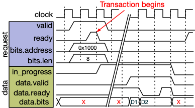
The request channel first exchanges a handshake with the address and transaction length payloads. Then, after an
indeterminate amount of time, the data for this transaction is returned. The data is not necessarily returned in
consecutive cycles. The next data associated with this transaction is only advanced when valid and reader are high
on the rising clock edge. The data (data.bits) will be held constant while data.ready is high and data.valid is
driven low.
Transaction Parallelism
Whereas a user may specify a single logical transaction (i.e., read 1GB of data starting from address 0x1000), it is Beethoven's
job to perform this transaction as quickly as possible. In practice, the FPGA/ASIC's memory link will not be saturated by a single
transaction. For our current platforms, the memory link is an AXI channel to a off-chip DRAM module. The AXI protocol provides a
number of ways to saturate the link performance.
First, longer transactions take better advantage of DRAM burst. However, AXI transactions are typically not allowed to cross page boundaries (4K). For this reason, our tranascations should be limited to 4KB.
If we want to read 1GB, we will need to issue many AXI transactions for one logical transaction. One way to do this is by using the AXI ID specifier to "tag" a transaction. There may be many transactions in flight simultaneously for a single AXI ID. These tranasactions are all guaranteed to execute in-order. This applies for both read and writes separately.
This ordering restriction limits our ability to take advantage of DRAM bank-level parallelism. To skirt this restriction, we issue transactions for a single logical transaction using many AXI IDs. This introduces additional complexity to our machinery but, in our experiments, results in higher memory performance. Transactions
On-Chip Memory (Scratchpad)
Beethoven offers two primary interfaces for using on-chip memory. The first is Scratchpad, which uses a similar flow to
the aforementioned Reader and Writer abstractions. Through this integration to the off-chip memory system, it offers a few
extra features. For users that want finer-grained control of their on-chip memory cells, there is also Memory. This
tool interacts with the platform-specific backend to instantiate FPGA BRAM and URAM cells or, on ASIC, interact with a
memory compiler for instantiating SRAM memory cells. A goal of these interfaces is to help the programmer to map efficiently
to memory cells without requiring manual planning - although this may occasionally be necessary especially for ASIC
targets.
Configuration
- Scratchpad Configuration
- ScratchpadFeatures
case class ScratchpadConfig(name: String,
                            dataWidthBits: Int,
                            nDatas: Int,
                            nPorts: Int,
                            latency: Number = 2,
                            features: ScratchpadFeatures = ScratchpadFeatures())
case class ScratchpadFeatures(readOnly: Boolean = false,
                              supportWriteback: Boolean = false,
                              supportMemRequest: Boolean = true,
                              specialization: ScratchpadSpecialization = ScratchpadSpecialization.flatPacked,
                              nBanks: Int = 1,
                              writeEnableMuxing: Boolean = false)
name: Unique identifier for fetching the scratchpad inside the core implementationdataWidthBits: In contrast to the byte-level precision of readers and writers,Scratchpaduses bit-widths.nDatas: the number of datums/rows in the memory array.nPorts: the number of read-write ports to the memory array (maximum of two is recommended for mapping to BRAM/URAM).latency: The latency of a read operation. FPGA memories can be cascaded to larger memories at the cost of latency.features: Scratchpads can be customized in a number of ways, but we provide a sensible default configuration that should only need to be changed in special circumstances.readOnly- [Default=false]: when enabled, all user-accessible ports will be read-only. This can allow for the use of Simple-Dual-Port BRAM functionalities in FPGA.supportWriteback- [Default=false]: when enabled, we elaborate a "writeback" engine inside scratchpad and a corresponding port in the request object. This allows the programmer to writeback the contents of the scratchpad to memory using a simple request handshake instead of needing to handle it themselves.supportMemRequest- [Default=true]: when enabled, we allow the user to initialize the scratchpad contents from external memory. LikesupportWriteback, this elaborates a corresponding port in the request channel.specialization- [Default=flatPacked]: because scratchpads operate at bit-granularity, but underlying readers and writers used for initialization and writeback use byte-granularity, we need to know how to unpack bits from payloads that may not align to data boundary.flatPacked- this assumes that the number of bits are power-of-two byte-aligned so there is really not much unpacking that needs to be done.PackedSubword- in other cases, the number of bits do not align to a byte boundary and so we introduce this alternative strategy. There is still some memory overhead here, but it can be minimized.
nBanks- [Default=1]: For deep, narrow memories, you may want to make better use of memory cells by putting more than one data on a row. You can increase this parameter to control the number of datas per row.writeEnableMuxing- [Default=false]: You can enable byte-wise write enable on the data port using this.
To retrieve the scratchpad inside your accelerator core, use getScratchpad(name: String).
- Fetch a Scratchpad
- Scratchpad Channel Type
- ScratchpadMemReqPort
- ScratchpadDataPort
def getScratchpad(name: String): ScratchpadModuleChannel
case class ScratchpadModuleChannel(
    requestChannel: ScratchpadMemReqPort,
    dataChannels: Seq[ScratchpadDataPort])
class ScratchpadMemReqPort(...)(implicit p: Parameters) extends Bundle {
  val init, writeback = Flipped(Decoupled(new Bundle() {
    val memAddr = Address()
    // scratchpad index to start filling from
    val scAddr = UInt(log2Up(nDatas).W)
    // number of bytes from memory to read in
    val len = UInt(Address.addrBits().W)
  }))
}
class ScratchpadDataPort(...) extends ScratchpadPort {
  // request to read/write from scratchpad
  val req = Flipped(Decoupled(new Bundle() {
    // index of the read
    val addr = UInt(scReqBits.W)
    // data input (if writing)
    val data = UInt(dataWidthBits.W)
    // active high, write enable
    val write_enable = Bool()
  }))
  // result of the read with an accompanying valid bit
  val res = ValidIO(UInt(dataWidthBits.W))
Like readers and writers, fetching a scratchpad requires the name it's associated with from the configuration. However, the request and data channels work differently for the case of on-chip memory. The memory request port allows the user to initialize the scratchpad with contents from memory, and the writeback port allows the user to write back the contents of the scratchpad to memory. When each of these transactions has completed, the ready signal for each of these signals will be driven high.
To access the data inside the scratchpad, use the dataChannels. The number of data channels is specified in the
configuration as nPorts. The input handshake uses both ready/valid. In some circumstances, the scratchpad may
not be ready to be ready to accept a request on a certain port. For instance, if the initialization/writeback
routines are in-progress, then one of the ports will be busy and unable to service reads/writes from the
programmer.
The data output from a scratchpad read has a delay corresponding to the latency given in the scratchpad configuration. A valid signal accompanies the data. The scratchpad does not have a ready signal for the data_out and it must be consumed when the data is valid.
On-Chip Memory (User-Managed)
For instantiating memory cells that are more directly-managed by the user, we provide the Memory interface.
On FPGA, this will instantiate vendor-provided templates for predictably mapping to memory cells, and for ASIC
targets, this will inspect the specified backend for a memory compiler. We provide more details for our ASIC
memory compiler support here.
- Memory Instantiation
- Memory IOs
Memory(latency: Int,
    dataWidth: Int,
    nRows: Int,
    nReadPorts: Int,
    nWritePorts: Int,
    nReadWritePorts: Int,
    withWriteEnable: Boolean = false,
    debugName: Option[String] = None,
    allowFallbackToRegister: Boolean = true)
class MemoryIOBundle(...) extends Bundle {
    val addr = Input(Vec(nPorts, UInt(addrBits.W)))
    val data_in = Input(Vec(nPorts, UInt(dataWidth.W)))
    val data_out = Output(Vec(nPorts, UInt(dataWidth.W)))

    val chip_select = Input(Vec(nPorts, Bool()))
    val read_enable = Input(Vec(nPorts, Bool()))
    // if byte-wise write-enable
    val write_enable = Input(Vec(nPorts, UInt((dataWidth / 8).W)))
    // if global write-enable
    val write_enable = Input(Vec(nPorts, Bool()))

    val clock = Input(Bool())

    def getReadPortIdx(idx: Int): Int
    def getWritePortIdx(idx: Int): Int
    def getReadWritePortIdx(idx: Int): Int

    def initLow(clock: Clock): Unit
}
Memory parameters:
latency: Like scratchpads, user-managed memory also takes a latency parameter. For FPGAs, the use of this is straightforward. For ASICs, we cascade memory cells to a similar effect (see here).dataWidth: bit-width of the memorynRows: number of rows in the memorynReadPorts,nWritePorts,nReadWritePorts: the number of each port to elaborate a memory for. For FPGA, there are special cases (e.g., SDP BRAMs) where using read-only and write-only ports can provide different results.withWriteEnable: by default, this is disabled. When enabled, the user will be provided a byte-wise write enable signal as opposed to a global write enable.debugName: the user can provide a name to annotate their memories by in the resulting RTL.allowFallbackToRegister: if the platform's supported memories do not allow for the requested configuration (e.g., too many ports), Beethoven will elaborate a register-based memory as a fallback routine. If you wish Beethoven to throw an error you can disable this.
The IOs for the memory are platform-agnostic and may, in reality, drive nothing if the signals are not used
on a specific platform. To identify which of the IOs correspond to the read/write/readwrite channels requested, use
the get<>PortIdx(idx) methods. For instance:
val my_memory = Memory(...,
    nReadPorts = 2,
    nWritePorts = 3,
    nReadWritePorts = 5,
    ...)
// tie off signals to make memory inactive by default
my_memory.init_low(clock)
val read_port_A = my_memory.getReadPortIdx(0)
val read_port_B = my_memory.getReadPortIdx(1)
// read ports can now be accessed using
my_memory.data_out(read_port_A)

// we can get port indices for our 0th, 1st, and 2nd write port
val write_port_C = my_memory.getWritePortIdx(0)
val write_port_D = my_memory.getWritePortIdx(1)
val write_port_E = my_memory.getWritePortIdx(2)
my_memory.data_in(write_port_D) := DontCare
We provide a init_low(clock: Clock) method to initialize the memory inputs to inactive.
All input signals to the memories are active-high, even if the underlying memory uses active-low inputs.
The latency of a write operation is always 1-cycle, even if the memory's specified latency is higher.
Host Interface
Users specify host-facing interfaces with BeethovenIO().
BeethovenIO takes in an AccelCommmand and AccelResponse implementation and generates host C++ linkage for
communicating with the accelerator core. You can instantiate multiple BeethovenIO() and it will generate
multiple host C++ interfaces.
AccelCommand
While we have supported arbitrary types inside AccelCommand in the past, maintaining the transformation between
arbitrary Chisel types and C++ is complex so we recommend using basic types for the most consistent results. The
recommended types are, UInt, SInt, Bool, and Address. These types may be at most 128b long. There is no
limit to the number of elements in the AccelCommand. We discuss memory allocation for the accelerator and the
associated Address type here.
Beethoven's host->HW interface is, for our current platforms, an 32-bit AXI-Lite port. For legacy reasons, we
encode commands using the RISC-V RoCC instruction format. RoCC instructions are a 32-bit instruction (which we
pack with routing information) and two 64-bit payloads. We pack the user-specified operands without fragmentation
into these payloads. Communicating a single instruction takes ~10µs over PCIE. Therefore, expect a multiple of
this delay for the number of 128-bit payloads necessary to communicate your AccelCommand.
AccelCommand takes a name as input. This will be used to construct the C++ host binding for this command.
The accelerator will be accessible from host as <Core-Name>::<Command-Name>.
AccelResponse
Responses are optional in Beethoven and are paired with a command. If a core does not respond to the core for
a given command, then the BeethovenIO does not need to specify a response. To return an empty acknowledgement
of completion for a command, you can use EmptyAccelResponse().
Beethoven also allows you to return a response with a payload up to 64-bits wide. For longer payloads, we recommend writing results to memory.
val my_io = BeethovenIO(...,
    AccelResponse(responseName) {
        ...
    })
The user provides a name for the accelerator response. This response will be the name of the response struct type. For instance:
- BeethovenIO
- Generated C++
// inside MyCore
val my_io = BeethovenIO(
    new AccelCommand("my_command"){...},
    new AccelResponse("my_response_t") {
        val a = UInt(4.W)
        val b = SInt(16.W)
    })
namespace MyCore {
    beethoven::response_handle<my_response_t> my_command(...);

    struct my_response_t {
        uint8_t a;
        int16_t b;
    };
}
Behavior of BeethovenIO
Both the command and response are coupled with ready/valid handshakes. For the command, the user drives the ready signal and for the response, the user drives the valid signal. The core should not drive the ready signal high until it has returned a corresponding response (if applicable). The core may accept commands without a corresponding response while processing another command. The core should not drive the response valid high while it is not processing a command.
Configuration + Build
An accelerator or a piece of an accelerator is described using an AcceleratorConfig. An AcceleratorConfig
is defined as one of a list of AcceleratorSystemConfig. AcceleratorConfigs can be concatenated with the
++ operator to conjoin accelerator descriptions.
case class AcceleratorSystemConfig(
    nCores: Int,
    name: String,
    moduleConstructor: ModuleConstructor,
    memoryChannelConfig: List[MemChannelConfig] = List(),
    canReceiveSoftwareCommands: Boolean = true,
    canIssueCoreCommandsTo: Seq[String] = Seq.empty,
    canSendDataTo: Seq[String] = Seq.empty
)
A "System" is a group of identical cores, which are identifiable by a unique name. This is the name that will form the namespace in the generated C++ linkage. The user may specify an arbitrary number of cores.
An Aside: Beethoven is built on top of RocketChip for use of its protocol Diplomacy framework. Because of this, you may see a
Parametersobject floating around in various interfaces.Parametersis a map object that allows us to look up various details about the current build without needing to pass around hundreds of of arguments.implicitis a Scala keyword that inspects the caller's scope for an implicit parameter of a given name and automatically passes in the parameter if it finds one.
moduleConstructor exposes the constructor of your accelerator core to the build system. There are multiple
options. There are two ways to do this. First, if you are developing your top-level module in Chisel, then you will use
ModuleBuilder which takes in a function that maps a Parameters object to an Accelerator Core. This is the most common
use-case. If you want nothing to do with Chisel, then you can also use BlackboxBuilderCustom to generate a Verilog shell
with a custom command/response interface.
case class BlackboxBuilderCustom(coreCommand: AccelCommand, coreResponse: AccelResponse) extends ModuleConstructor
memoryChannelConfig is where you provide a list of memory interfaces (e.g., Readers, Writers) for a core in this sytem.
If you intend for an accelerator core to only be internally visible (other cores can communicate with it but not the host,
then you can specify this using canReceiveSoftwareCommands. In such circumstances, we also need to define the communication
topology for these intercommunicating cores. You specify the ways in which cores may communicate with other systems using
canIssueCoreCommandsTo and canSendDataTo and providing the names of the systems.
Building your Accelerator
Now that you've constructed an accelerator configuration, you can use a BeethovenBuild object to construct your accelerator
for a given platform like so.
object MyAcceleratorBuild extends BeethovenBuild(new MyAcceleratorConfig,
    buildMode = <BuildMode>,
    platform = <Your Platform>)
// you will see 'MyAcceleratorBuild' as an option when you run `sbt run` in the top directory.
First, you must specify which platform you are building your hardware for. We have currently two well-supported FPGA platforms, the Kria KV260, and the AWS F1/F2 cloud FPGA instances.
Beethoven has two build modes: BuildMode.Synthesis and BuildMode.Simulation. When building for synthesis, we generate the
hardware and run a platform-specific
Platforms
Current Platforms
- AWS F1/F2 [link] [GitHub] - AWS offers cloud-FPGAs at a reasonable hourly price for those who aren't ready to drop $15,000 on a new datacenter FPGA. AWS has recently phased-out use of the F1 platform and we are transferring this functionality over to the F2. See here for a walkthrough on deploying a design on AWS F2.
- Zynq Ultrascale+ Series - The Zynq MPSoCs feature a dual-Core ARM A53 capable of running Linux. We use the Kria KV260 for our development purposes. See here for a walkthrough on deploying a design on Kria.
- ASIC Test Chip - We are taping out a chip using Beethoven! Check back in a few months to see if the chip works. If you are interested in this, contact the authors. This functionality is actively in-development and some of the implementation in conjunction with Beethoven may require some tinkering to make it "open-source"-able.
If you're interested in developing your own platform, read here.